


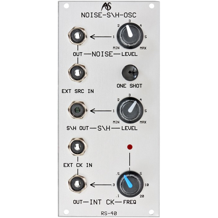
Analogue Systems RS-40 Sample and Hold \ Noise \ Clock
Analogue Systems RS-40 Sample and Hold \ Noise \ Clock
Couldn't load pickup availability
Clock Generator, Noise Source and Sample and Hold
- 12 hp
- 2.5 inches Depth
- 25 mA +/-12V
The RS40 Noise Generator / Sample & Hold / Clock is really three separate sub-modules that you can patch together to help generate classic Sample & Hold effects. But effects are far from the only uses for the sub-modules, and they can be patched into other RS Integrator modules for an even wider range of effects.
Noise Generator
INTRODUCTION
Most audio oscillations are 'periodic': that is, when displayed on a screen, they exhibit a recognisable shape that repeats and repeats and repeatsナ The best known examples of periodic waveforms are the sine waves, triangle waves, pulse waves, and sawtooth waves produced by Integrator modules such as the RS90 VCO and RS80 LFO.
Not all audio frequency oscillations exhibit this repetitious nature, and the most common of these 'aperiodic' waves is called "white noise". But why "white" and why "noise"? Let's explain each in turnナ
A signal is perceived as noisy if it is random. Described another way, pure noise contains no discernible frequencies or tones.
But some noises may be described as rumbles, hisses, or even shrieks. In each of these cases, the waveform itself is random, but the signal only contains a narrow band of frequencies. Audible noise may, therefore, be "coloured" in exactly the same way that visible light is. If lower frequencies predominate, the noise has a deep, rumbling character, and it is called 'pink' or 'red' depending upon its exact nature. If high frequencies predominate the noise is called 'blue'. But if all frequencies are present in each amplitudes, the noise is 'white'. This is exactly analogous to light, where the presence of all the visible frequencies at equal amplitudes is perceived by the eye as the colour 'white'.
White Noise is, therefore, a signal that contains all the audio frequencies in equal amounts, but which manifests no recognisable pitches or tones. Another definition is this: a white noise signal is one in which the probability of a frequency being present is equal to the probability of any other frequency being present.
Many natural sounds display noisy characteristics - the crashing of waves and the howl of a strong wind are prime examples of these - and it would be impossible to synthesise such sounds without a noise generator. Many musical instruments also generate noise, although the amplitude of this part of the signal is generally low, and its colour is largely dependent upon the instrument. But if you start with white noise you can filter it to produce all other 'colours' of noise. You can also use resonant filters to accentuate certain frequencies, and modulate the noise amplitude to create such things as chiffs or wind and wave effects.
IN USE Some synthesisers offer 'noise' as an option on the main audio oscillators. This has a significant drawback: if your oscillators are acting as noise generators they are not outputting conventional waveforms. This can be very limiting and, for this reason, the Integrator's noise generator is provided on a separate module.
Unlike a standard oscillator, the Noise Generator requires no controls for its waveform or its frequency. There is, therefore, just one control and one output. There is no input.
LEVEL
The only method of controlling the Noise Generator is by adjusting the LEVEL knob. Turning this from its minimum to its maximum will cause the RS40 to produce white noise in the range 0V (fully anticlockwise, and silent) to ᄆ_2.5V (fully clockwise).
OUT
The noise is output from the associated OUT socket.
Sample And Hold
INTRODUCTION
Sample & Hold (S&H) circuits provide many of the most recognisable 'synthesiser' sounds by making modules such as oscillators and filters 'step' between values, thus creating rapidly varying patterns of pitch or timbre. They do so like thisナ
The S&H circuit produces stepped voltages by 'sampling', and then 'holding' the instantaneous value of any signal presented at its input. This signal could be a CV, an external signal such as the music from a CD or the sound of an instrument being played. Most commonly, however, a noise source is used because this creates a number of musically pleasing 'random' effects.
The circuit samples the incoming signal voltage when it is told to do so by an external trigger, usually provided by some form of clock or other triggering pulse. The voltage thus measured will then be held and presented to the output until the next trigger is received, at which time a further sample will be made, and the voltage at the output assumes its new value.
When the S&H output is presented to an oscillator's CV input it causes the pitch of the oscillator to follow the instantaneous amplitude of the signal presented to the S&H input. If directed to a filter, the S&H value determines the cutoff frequency of the filter, and therefore affects the brightness or timbre of any signal passing through that filter. Of course, the S&H circuit's output can be directed to all other modules, and can be used to modify any of the CVs or signals within the synthesiser.
IN USE
The RS40 incorporates a highly stable S&H circuit that will sustain a constant voltage almost indefinitely. Because it provides external inputs for the signal to be sampled and for the trigger, it can be used with any signals, not just a noise source and a clock. The inputs are the source signal input (EXT SRC IN) and the trigger input (EXT CLK IN). The output is... well, the output. The controls are an output level control, and a manual trigger (ONE SHOT).
EXT SRC IN
This input accepts signals in the range ᄆ10v. These signals may be CVs or audio signals, and may be generated within the RS Integrator or presented by outside sources such as CDs, microphones, or other musical instruments. If the signal amplitude is too low for effective use as a source, you should use the Pre-Amp sub-module in the RS70 to boost it to an appropriate level.
EXT CLK IN
This input will generate a trigger when it receives any positive-going waveform with a sharp leading edge. A pulse wave is the traditional signal to use for this, but almost any waveform will suffice - even sine waves above about 3Hz will provide a trigger. Note, however, that not all waves will cause the S&H to trigger in the same fashion.
For example, a sawtooth with a trailing edge produces a pronounced 'click' compared to a sawtooth with a leading edge. Furthermore, sawtooth waves will often trigger the S&H more frequently than a pulse wave of the same frequency. It has even been observed that different waveforms presented at the clock input will lead to different ranges of voltages being produced by the S&H circuit itself. You should use the RS80 LFO to experiment with these effects.
LEVEL
The LEVEL control adjusts the range of voltages produced by the S&H. Think of it as a 'range' control: the source may exhibit variations of ᄆ10V, but the LEVEL allows you to compress this to any range of voltages from 0V (fully anticlockwise, no effect is generated) to the full ᄆ10v (fully clockwise).
ONE SHOT
If no signal is presented to the EXT CLK IN socket, you can take a sample by pressing the ONE SHOT button. This will cause the S&H circuit to measure the instantaneous amplitude of the signal presented to the EXT SRC IN socket, and hold it until the next time you press the button.
S&H OUT
Sampled voltages, once scaled by the LEVEL control, are output here. The maximum signal amplitude is ᄆ10v.
Clock
IN USE
A clock is simply another form of oscillator: one that produces a pulse wave at, typically, subsonic and low audio frequencies. It is most often used as a timer - for example, triggering envelopes and sample & hold circuits - but can also used as a 'sync' or reset source for conventional audio oscillators and LFOs.
FREQ
You control the Clock frequency by adjusting the FREQ knob. Turning this from its minimum to its maximum will cause the RS40 to produce clock pulses in the range 0.1Hz (fully anticlockwise) to approximately 30Hz (fully clockwise).
OUT
The level of the clock pulse wave is fixed at ᄆ10V.
Status LED
The status LED gives you a direct visual indication of clock rate.
Putting It All Together
Unlike some other synthesisers with S&H modules, the three sub-modules in the Integrator are not pre-connected "behind the scenes". (If they were, the "one shot" button would not work.)
This means that you must patch sources into both the EXT SRC IN and EXT CLK IN sockets. The simplest and most obvious sources for these purposes are the noise generator and the clock, so now you should:
patch from the NOISE OUT to the EXT SRC IN
patch from the INT CK OUT to the EXT CLK IN
set the NOISE LEVEL to maximum
set the CLOCK FREQ to a midway position (12 o'clock)
set the S&H LEVEL to maximum
At this point, the S&H OUT socket will be producing a random stepped CV in the range ᄆ10v. You can now direct this to the input of your choice. The most common destinations are the audio oscillators and the filters. To apply S&H to either of these, patch the S&H OUT to either the CV-IN VARY on the RS90 VCO or the CV-IN VARY of the RS100 VCF. If you then increase the associated LEVEL control on the destination module the RS Integrator will, all other things being patched appropriately, produce a randomly stepped pitch or randomly stepped brightness effect.
Share
