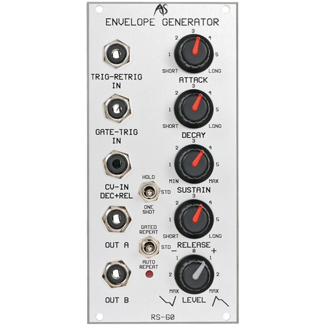


RS-60 Envelope Generator
RS-60 Envelope Generator
Couldn't load pickup availability
Voltage Controlled ADSR Envelope Generator
- 12 hp
- 2.5 inches Depth
- 24 mA +/-12V
INTRODUCTION
Periodic waveforms - such as those produced by VCOs and LFOs - have easily recognised pitches, amplitudes and waveforms that you can spot on an oscilloscope or screen. (For a brief discussion of these please turn to the chapters dedicated to the RS80 LFO and RS90 VCO.)
Non-periodic waveforms, or 'noise', have random form, and while they are continuous, they contain no easily discernable pitches or amplitudes. (See the chapter on the RS40.)
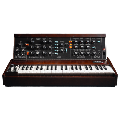
But not all waveforms conform to these models. In particular, there is one type of waveform that is often not recognised as a wave at all. This is because it is used almost exclusively to 'shape' or 'contour' other signals. On some synthesisers (such as the Minimoog) the circuit that produces this class of waves is even called a 'contour', but its most common name is an 'Envelope Generator'.
For an introductory discussion on envelope generators and their uses, please refer to appendix 3 at the back of this manual.
IN USE
The RS60 Envelope Generator is a flexible EG that generates a four-stage ADSR voltage envelope that varies from 0V to +10V. The envelope can be attenuated and inverted if desired.
At their minimum values the A, D and R stages offer very rapid responses of better than 0.5mS, thus making the Integrator much 'snappier' than other analogue synths that often offer minimum attack times as slow as 5mS - 10mS. The S stage allows you to apply gains ranging from -�dB to 0dB (unity gain) to the steady-state level.
The RS60 offers a CV input that extends or shortens the Decay and Release times for sustained effects. There are also two switches that allow you to trigger the envelope manually, prevent it from re-triggering, auto-repeat once it has completed its profile, and so on. Modulating the envelope and using combinations of the retrigger switches allows you to generate complex envelope and low-frequency oscillations.
Trigger & Gate Inputs
In normal use the envelope is generated when the module receives a gate pulse or is triggered by a specific input. The RS60 offers two such inputs:
TRIG-RETRIG IN In standard use, the positive-going edge of any waveform presented to this input is treated as a trigger pulse of negligible duration. This is equivalent to pressing down a key and releasing it immediately. More complex uses for this input are described in the section on Mode Switches (below).
GATE-TRIG IN If the voltage of any waveform presented to this input reaches +1V it is treated as a gate that is held open until the voltage drops below +1V.
ATTACK
The Attack is initiated upon receipt of a trigger or gate, and the unattenuated output voltage will rise from 0V to +10v in the time determined by the ATTACK knob. The minimum attack time is 0.5mS. The maximum is approximately 10S.
DECAY
Provided that a Gate still exists at the completion of the attack, a decay phase immediately follows. The unattenuated output voltage will fall from +10v to the level determined by the SUSTAIN level in the time determined by the decay knob. The minimum decay time is 2.5mS. The maximum is approximately 20S.
SUSTAIN
The Sustain knob determines the level of the sustained portion of the envelope, and has an unattenuated range of 0V to +10v. The sustain phase only occurs when a Gate is used, or when the envelope is 'held' by the appropriate toggle switch (see below).
RELEASE
The Release is initiated at the moment the Gate or Trigger ceases. The unattenuated output voltage will fall from the level determined by the Sustain level to 0V in the time determined by the Decay knob. The minimum Release time is 2.5mS. The maximum is approximately 20S.
LEVEL
The output level and polarity are controlled by the LEVEL control. With this turned fully clockwise, the envelope will be output without attenuation. As you turn the knob anticlockwise, the signal will be attenuated until, with the knob in the 12 o'clock position, no envelope is generated. As you continue to turn the LEVEL knob anticlockwise, an attenuated inverted envelope will be output until, at the knob's fully anticlockwise position, the inverted envelope is output without attenuation.
OUT A; OUT B
Two outputs are provided. These carry identical signals so you can direct the envelope to two destinations simultaneously.
Mode Switches
Two mode switches are provided, and these modify the action of the envelope generator. There are nine combinations of the two switches, and these act as follows:
STD / STD
The STD (standard) setting is the normal mode of operation for conventional ADSR envelope generation using a Gate pulse to initiate and hold the envelope.
HOLD / STD
In general, the HOLD position holds the envelope voltage at the level determined by the sustain control. However, the way in which it does this is further modified by whether the
GATE-TRIG IN or the TRIG-RETRIG IN is used.
GATE-TRIG IN All triggers and gate pulses are ignored, and the envelope is permanently held at the S level. The A, D and R phases are not used.
TRIG-RETRIG IN
A new trigger or gate pulse will retrigger the A and D phases of the envelope, before holding at the S level. The R phase is not used.
ONE SHOT / STD
You may provide a manual Gate by depressing the switch to the ONE SHOT position. The envelope will enter the R phase when you release the switch.
Triggers received at TRIG-RETRIG IN will cause the envelope to repeat for as long as the ONE SHOT switch is depressed.
HOLD / GATED REPEAT
HOLD / AUTO REPEAT
These combinations have the same effect.
The REPEAT functions cause the envelope to generate an output determined by the A and D settings, then repeat. Consequently, the RS60 is capable of generating a considerable range of repeated AD curves that may be used as LFOs or even audio frequency oscillations, the frequency of which are defined by the time taken to complete one AD cycle. (Modulating the Decay - see below - then makes many other waveforms possible.)
The maximum repeat rate is approximately 300Hz.
The minimum repeat rate is approximately 0.03Hz
The REPEAT function is further modified by whether the GATE-TRIG IN or the TRIG-RETRIG IN is used.
GATE-TRIG IN
All triggers and gate pulses are ignored.
TRIG-RETRIG IN
A gate will hold the envelope at +10V. In the absence of a Gate, the REPEAT will occur as before.
STD / GATED REPEAT This combination allows the envelope to repeat only when a Gate is presented to the GATE-TRIG IN. Signals presented to the TRIG-RETRIG IN have no effect.
STD / AUTO REPEAT GATE-TRIG IN This combination allows the envelope to repeat whether or not a Gate signal is presented to the GATE-TRIG IN, and any such Gates are ignored.
TRIG-RETRIG IN
If a Gate signal is presented to the TRIG-RETRIG IN, the envelope will be held at +10v while the Gate is received, and will REPEAT in the absence of the Gate.
ONE SHOT / GATED REPEAT
ONE SHOT / AUTO REPEAT
These combinations have the same effect.
The ONE SHOT position acts as a Gate pulse for the duration that you hold it in that position. With either GATED REPEAT or AUTO REPEAT also selected, the envelope will act in two ways, as follows:
TRIG-RETRIG IN
If a Gate signal is presented, the envelope will be held at +10v while the Gate is received. If no Gate signal is presented to the TRIG-RETRIG IN, the envelope will REPEAT for as long as you hold the switch down.
GATE-TRIG IN
Signals presented to the GATE-TRIG IN have no effect.
You can use the repeating options to turn the RS60 into a sophisticated LFO, and the gated repeats can be used to generate sophistic poly-rhythmic effects. If the A and D times are short enough you can generate audible frequencies, and very complex waveforms can be obtained if you use fast LFOs or other audio frequency signals to retrigger the envelope.
The maximum repeat rate is approximately 300Hz.
The minimum repeat rate is approximately 0.03Hz
CV-IN D&R
You can modulate the Decay and Release times by presenting a positive CV to this input. A CV of 0V has no effect, while a CV of +10v will shorten the times to their minimums. This is particularly useful for key-scaling the envelope to imitate the responses of the many natural sounds and instruments that become shorter in duration as their pitch increases. Another use if for emulating the response of a 'damper' function in plucked and hammered sounds.
Status LED
The red LED gives you a direct visual indication of the voltage being produced by the RS60. When it is at its brightest, the envelope has reached +10V. When it is extinguished, no voltage is being produced. The position of the master level attenuater / inverter has no effect on the LED.
Share