


1
/
of
1
WMD Multimode VCA
WMD Multimode VCA
Regular price
$ 229.00 USD
Regular price
Sale price
$ 229.00 USD
Unit price
/
per
Shipping calculated at checkout.
Couldn't load pickup availability
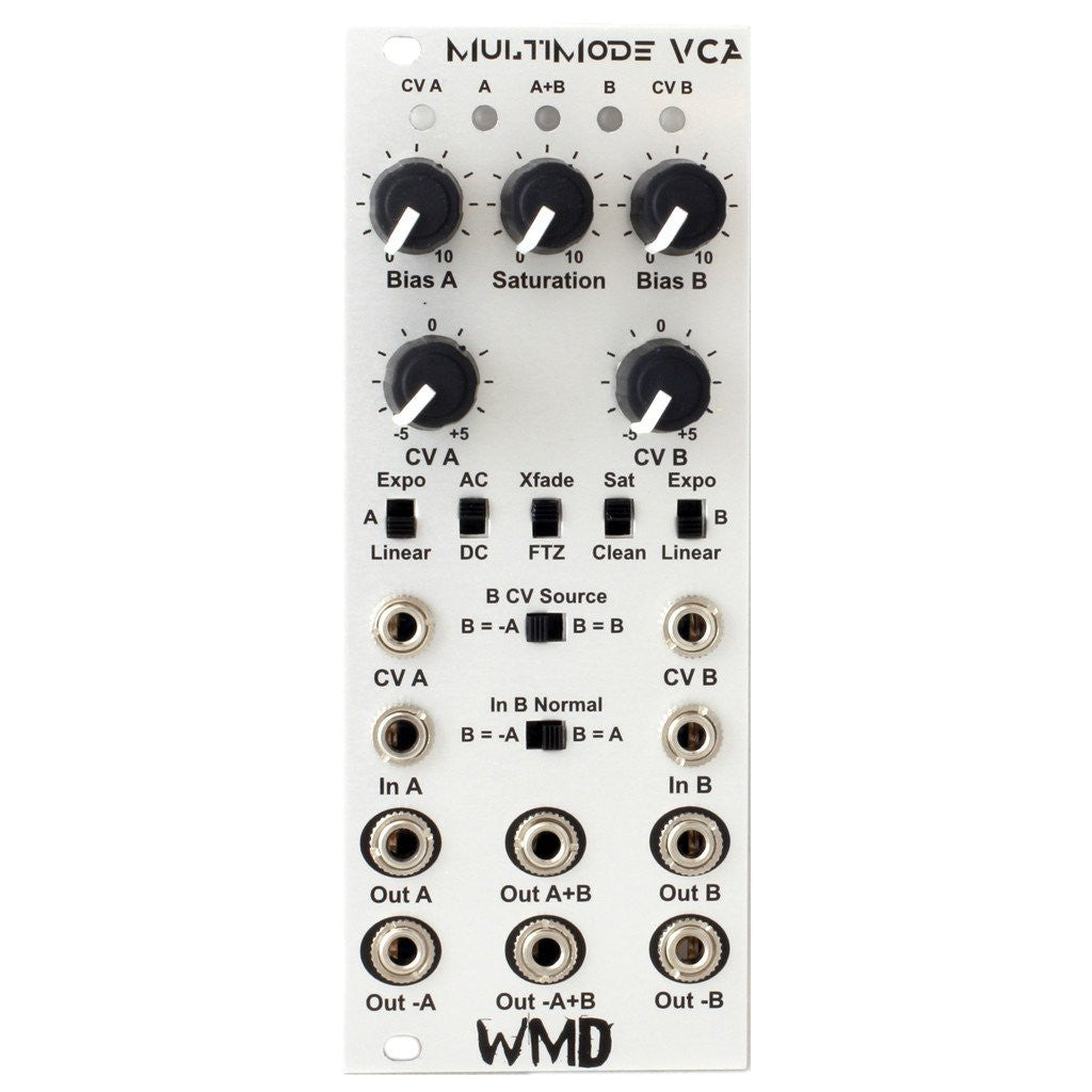
The WMD Multimode VCA is designed to be the most versatile amplifier in your modular. Period.
The MMVCA is capable of a number of useful configurations utilizing both VCAs, or as two seperate amplifiers. It has plenty of headroom in "clean" mode or can be easily overdriven with the soft saturation circuit. You'll want to run everything through the MMVCA.
SPLIT MODE - The MMVCA serves as two separate VCAs in this mode. Set the B CV Source switch to B = B. Plug into both VCAs and use separate CV, or just the CV from the A jack.
BIPLOAR VCA - This mode requires the use of both A and B channels. Set both the B CV Source and In B Normal switches to B = -A. Plug CV and signal to be polarized into the A side. Monitor from A + B. The output will be inverted through zero at 0V CV.
CROSSFADE - Run two inputs to the A and B Jacks. Set the Xfade/FTZ switch to Xfade when in linear operation. Set the B CV Source switch to B = -A. Control crossfade with the CV A jack. Monitor on A+B Out. Works similarly in Exponential mode.
FADE THROUGH ZERO - Both VCAs set to Linear mode. Set the Xfade/FTZ switch to FTZ. Set the B CV Source switch to B = -A Control with CV A jack. Monitor on A+B Out. This fades B to silence to A as CV goes positive.
PAN - Run audio into the A jack. Set the In B Normal switch to B = A. Set the Xfade/FTZ switch to Xfade. Monitor in stereo on both A and B Outputs. CV A will move right to left (B to A) as CV goes positive.
SPREAD PAN - Run audio into the A jack. Set the In B Normal switch to B = A. Set the B CV Source switch to B = B . Audio in A, CV in A. Oppose the CV knobs to control response to CV. Use the Bias knobs to set the amount of spread. Monitor in stereo on both A and B Outputs.
SPREAD CROSSFADE - Run audio into both the A and B jacks. Set the In B Normal switch to B = A. Set the B CV Sourceswitch to B = B . Audio in A, CV in A. Oppose the CV knobs to control response to CV. Use the Bias knobs to set the amount of spread. Monitor the A+B.
Controls and I/O
CV A & CV B - These jacks and bipolar CV attenuators control the CV for each VCA. Set the knob to the center for no CV. Spin CW for normal CV operation, CCW for inverted CV operation. The CV A jack is normaled to the input of the CV B jack. The CV B jack will be disabled by setting B CV Source to -A. Green LEDs on the top right and left sides indicate the strength of the CV signal applied to each VCA.
IN A & IN B - These jacks are for the injection of any signal. They can be DC or AC coupled.
OUT A & OUT B - These jacks are the phase matched outputs for each side. These can be DC or AC coupled. The two bicolor LEDs at the top marked A and B will indicate output strength and polarity. Red for negative voltages, and blue for positive.
OUT -A & OUT -B - These jacks are inverted outputs for each side. If AC coupled, these jacks are buffered after the DC offset removal. The center bicolor LED at the top marked A+B indicates signal strength and polarity. Red for negative voltage, and blue for positive.
OUT A+B - This is the summed output of both VCAs.
OUT -A+B - This is the summed inverted output of both VCAs.
BIAS A & BIAS B - These knobs control the ambient amplification of each VCA. In Linear and FTZ modes, set to center will produce no output. In Xfade mode, fully CCW will produce no output.
LINEAR / EXPO SWITCH - One switch for each channel. Selects the mode of operation for the VCA. Expo mode has a trimmer on the back to set the sensitivity to CV.
AC / DC SWITCH - This switch introduces capacitors to the inputs and outputs of both channels. AC mode can eliminate the minor DC offset produced by the VCAs. This introduction of capacitors causes a minor rolloff at low frequencies. The -6dB/octave rolloff begins at roughly 85Hz. This frequency was selected to eliminate the settling effect of lower cutoff frequencies.
Xfade / FTZ SWITCH - This switch is only operational in Linear mode. It introduces a DC offset to the CV of both channels allowing for smooth crossfades between the two channels. Fade Through Zero mode produces a silent center where both VCAs are simultaneously off at 0 volts CV input.
SAT / CLEAN SWITCH & SATURATION KNOB - This switch enables the variable saturation circuit controlled by the knob. When off, the VCAs will hard clip at 20Vpp. When on and Saturation is fully CCW, the peaks will begin to be rounded off starting at 11Vpp. The signal can still hard clip at 20Vpp. Turn Saturation CW and the circuit will compress the waveform more, adding a little bit of nice distortion. Turn Saturation fully CW for thick distorted waveforms with nice round peaks. Fully CW limits the output voltage to roughly 8Vpp.
B CV SOURCE - Selects whether to look at the B CV jack and attenuator, or to override the input with the inverted CV signal from channel A.
B IN NORMAL - Selects whether the signal normaled to the B In jack is the straight signal from A, or the inverted signal from A. Use for Bipolar VCA mode.
The MMVCA is capable of a number of useful configurations utilizing both VCAs, or as two seperate amplifiers. It has plenty of headroom in "clean" mode or can be easily overdriven with the soft saturation circuit. You'll want to run everything through the MMVCA.
- Two Factory-Trimmed OTA VCAs
- Exponential & Linear Response
- Bipolar CV Attenuators
- Intelligent Normaling
- AC / DC I/O Signal Coupling
- Variable Saturation/Soft Clipping
- Sum Outputs
- Inverted Outputs
- Green CV LEDs
- Signal LEDs - Blue (+) / Red (-)
- 20Vpp Clean Output Range
- +40mA/-40mA Current Consumption
- 10 HP
- Skiffable
SPLIT MODE - The MMVCA serves as two separate VCAs in this mode. Set the B CV Source switch to B = B. Plug into both VCAs and use separate CV, or just the CV from the A jack.
BIPLOAR VCA - This mode requires the use of both A and B channels. Set both the B CV Source and In B Normal switches to B = -A. Plug CV and signal to be polarized into the A side. Monitor from A + B. The output will be inverted through zero at 0V CV.
CROSSFADE - Run two inputs to the A and B Jacks. Set the Xfade/FTZ switch to Xfade when in linear operation. Set the B CV Source switch to B = -A. Control crossfade with the CV A jack. Monitor on A+B Out. Works similarly in Exponential mode.
FADE THROUGH ZERO - Both VCAs set to Linear mode. Set the Xfade/FTZ switch to FTZ. Set the B CV Source switch to B = -A Control with CV A jack. Monitor on A+B Out. This fades B to silence to A as CV goes positive.
PAN - Run audio into the A jack. Set the In B Normal switch to B = A. Set the Xfade/FTZ switch to Xfade. Monitor in stereo on both A and B Outputs. CV A will move right to left (B to A) as CV goes positive.
SPREAD PAN - Run audio into the A jack. Set the In B Normal switch to B = A. Set the B CV Source switch to B = B . Audio in A, CV in A. Oppose the CV knobs to control response to CV. Use the Bias knobs to set the amount of spread. Monitor in stereo on both A and B Outputs.
SPREAD CROSSFADE - Run audio into both the A and B jacks. Set the In B Normal switch to B = A. Set the B CV Sourceswitch to B = B . Audio in A, CV in A. Oppose the CV knobs to control response to CV. Use the Bias knobs to set the amount of spread. Monitor the A+B.
Controls and I/O
CV A & CV B - These jacks and bipolar CV attenuators control the CV for each VCA. Set the knob to the center for no CV. Spin CW for normal CV operation, CCW for inverted CV operation. The CV A jack is normaled to the input of the CV B jack. The CV B jack will be disabled by setting B CV Source to -A. Green LEDs on the top right and left sides indicate the strength of the CV signal applied to each VCA.
IN A & IN B - These jacks are for the injection of any signal. They can be DC or AC coupled.
OUT A & OUT B - These jacks are the phase matched outputs for each side. These can be DC or AC coupled. The two bicolor LEDs at the top marked A and B will indicate output strength and polarity. Red for negative voltages, and blue for positive.
OUT -A & OUT -B - These jacks are inverted outputs for each side. If AC coupled, these jacks are buffered after the DC offset removal. The center bicolor LED at the top marked A+B indicates signal strength and polarity. Red for negative voltage, and blue for positive.
OUT A+B - This is the summed output of both VCAs.
OUT -A+B - This is the summed inverted output of both VCAs.
BIAS A & BIAS B - These knobs control the ambient amplification of each VCA. In Linear and FTZ modes, set to center will produce no output. In Xfade mode, fully CCW will produce no output.
LINEAR / EXPO SWITCH - One switch for each channel. Selects the mode of operation for the VCA. Expo mode has a trimmer on the back to set the sensitivity to CV.
AC / DC SWITCH - This switch introduces capacitors to the inputs and outputs of both channels. AC mode can eliminate the minor DC offset produced by the VCAs. This introduction of capacitors causes a minor rolloff at low frequencies. The -6dB/octave rolloff begins at roughly 85Hz. This frequency was selected to eliminate the settling effect of lower cutoff frequencies.
Xfade / FTZ SWITCH - This switch is only operational in Linear mode. It introduces a DC offset to the CV of both channels allowing for smooth crossfades between the two channels. Fade Through Zero mode produces a silent center where both VCAs are simultaneously off at 0 volts CV input.
SAT / CLEAN SWITCH & SATURATION KNOB - This switch enables the variable saturation circuit controlled by the knob. When off, the VCAs will hard clip at 20Vpp. When on and Saturation is fully CCW, the peaks will begin to be rounded off starting at 11Vpp. The signal can still hard clip at 20Vpp. Turn Saturation CW and the circuit will compress the waveform more, adding a little bit of nice distortion. Turn Saturation fully CW for thick distorted waveforms with nice round peaks. Fully CW limits the output voltage to roughly 8Vpp.
B CV SOURCE - Selects whether to look at the B CV jack and attenuator, or to override the input with the inverted CV signal from channel A.
B IN NORMAL - Selects whether the signal normaled to the B In jack is the straight signal from A, or the inverted signal from A. Use for Bipolar VCA mode.
Share